Contents - Index - Previous - Next
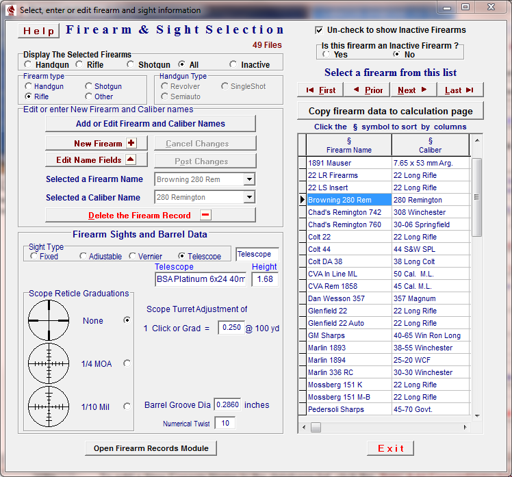
Firearm Name and Sight List
Select or click on the Firearm Select button on the Data Entry page to open this Firearm and Sight module.
This database list is used to store individual firearm names and sight configurations that may be used in the ballistics and trajectory calculations.
After selecting a firearm sight configuration, the data may be entered into the appropriate configuration fields on the Data Entry page by clicking on the ![]() button.
button.
To add a New Firearm Name to the database list, click the ![]() button. This will open the Add / Edit Names form.
button. This will open the Add / Edit Names form.
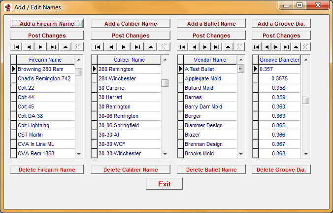
Click the ![]() button to open a new, blank Firearm Name Record
button to open a new, blank Firearm Name Record
Type in a unique, descriptive name for the firearm and then press the ![]() key to fix the name into the entry field.
key to fix the name into the entry field.
If the caliber name of the New Firearm is not in the Caliber Name List click the ![]() button and type in the correct caliber name. The Caliber Name should not be a decimal number such as is required for the various ballistic coefficient and trajectory calculations but should be a nominal description such as "30-06 Rem", "30-30 Win" or "357 Mag".
button and type in the correct caliber name. The Caliber Name should not be a decimal number such as is required for the various ballistic coefficient and trajectory calculations but should be a nominal description such as "30-06 Rem", "30-30 Win" or "357 Mag".
click the ![]() to fix the caliber name into the entry field.
to fix the caliber name into the entry field.
Return to the Firearm and Sight Selection form and click on the ![]() button at the top of the page. This will open a new, blank record in the firearm database and open the drop-down list of firearm names where the New Firearm Name may be selected.
button at the top of the page. This will open a new, blank record in the firearm database and open the drop-down list of firearm names where the New Firearm Name may be selected.
When the firearm name is selected the Caliber Name drop-down list will open and the caliber of the New Firearm may be selected.
Click the ![]() button to post the New Firearm Name and Caliber in the Arms Record Database.
button to post the New Firearm Name and Caliber in the Arms Record Database.
After any load information has been entered for a firearm, do not edit or change the Firearm Name or Caliber Name as the software will not be able to locate and display any information associated with the firearm.
A Firearm may be removed from the database by clicking the ![]() button. This will delete the SELECTED FIREARM and all records associated with the Selected Firearm in all the Precision Records Databases.
button. This will delete the SELECTED FIREARM and all records associated with the Selected Firearm in all the Precision Records Databases.
Once the New Firearm Name and Caliber have been entered, go to the Sight Selection radio button panel and select the type of sight installed on the firearm. This will open the appropriate entry fields that are associated with the type of sight selected.
You may enter a brief name or description of the front and rear sights in the fields provided.
*************************************************************************************
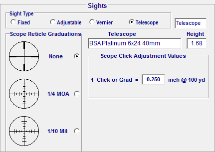
If a telescope sight configuration is selected, the amount of bullet strike movement per click must either be determined from the information supplied by the 'scope manufacturer or from actual experimentation and measurements and then manually entered into the value field. Usually the value is 1/4 inch, but not always, so care should be taken to arrive at the correct value.
TELESCOPE SIGHTS
Scope height is measured from the center of the bore to the center of the telescope. A measuring method that works well with scopes is ~ using calipers, measure the distance from the top of the telescope to the bottom of the barrel. Then measure the diameter of the barrel and the diameter of the scope and subtract 1/2 of each diameter from the first measurement.
*************************************************************************************
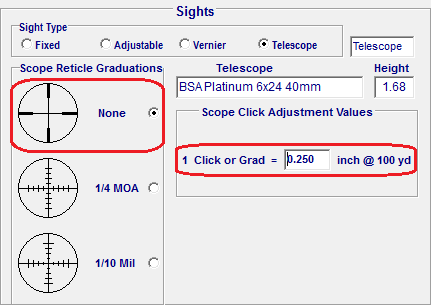
If entries are being entered for a telescope sight that has no graduations on the reticle, select the radio button titled "None" in the Scope Reticle Box. The telescope manufacturer's advertised adjustment increments may be used or the impact movement per click may be physically measured with firing tests.
*************************************************************************************
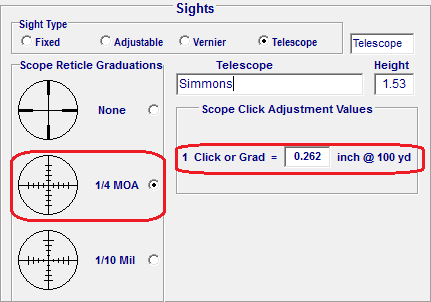
If The scope reticle is etched with Minute of Angle graduations, select the radio button titled "1/4 MOA" and the software will enter a value of 0.262" of impact movement per click at 100 yards.
A Circle defined by angular units is divided into arcs of 360 degrees x 60 minutes = 21, 600 minutes of angle or M.O.A.
1 / 4 M.O.A. of impact movement at 100 yards is determined by:
100 yards x 3 x 12 = 3,600 inches @ 100 yards.
The diameter of a circle with a radius of 100 yards is 2 x 3,600 = 7,200 inches.
The circumference of a circle with a radius of 100 yards is Pi (3.14159) x 7,200 = 22, 619.47 inches.
Divide the circumference of the circle by 360 degrees = 22,619.47 / 360 = 62.83185 inches per degree.
One degree of angle contains 60 minutes so divide again by 60 : 62.83185 / 60 = 1.04719 inches per minute of angle at 100 yards.
1/4 minute of angle = 1.04719 / 4 = 0.262 inches of impact movement at 100 yards
*************************************************************************************
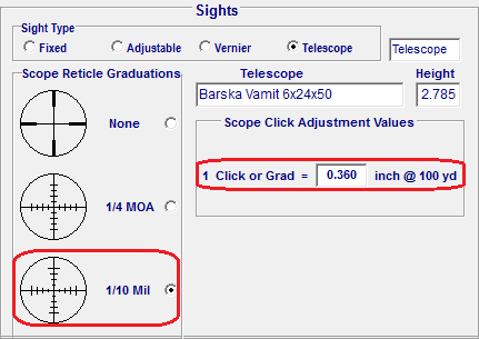
If the scope reticle is etched with Mil Dot graduations, select the radio button titled "1/10 Mil" and the software will enter a value of 0.36" of impact movement per click at 100 yards.
A Circle defined by miliradian units is divided into arcs of 6,283.2 miliradians or MILs.
A Circle with a radius of 100 yards has a diameter of 22, 619.47 inches.
A Mil divides the circumference of a circle with a radius of 100 yards into segments of 3.6 inches.
22, 619.47 / 6,283.2 = 3.6 inches.
1 / 10 Mil of impact movement at 100 yards is determined by:
3.6 / 10 = 0.36 inches of impact movement at 100 yards.
*************************************************************************************
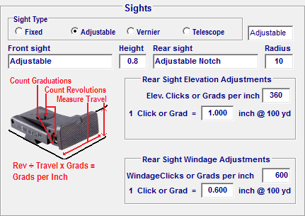
ADJUSTABLE SIGHTS
An adjustable sight configuration causes the next 5 entry boxes to become visible. In the first field, enter the height, in inches, of the front sight above the axis of the bore.
Graduations per inch on adjustable sights may be calculated by determining the threads per inch on the screw adjustment and then, multiply the threads-per-inch value by the number of clicks, stops or marks on the circumference of the adjusting screw to get the clicks or graduations per inch.
The next adjustable sight configuration entry is the distance, in inches, from the rear face of the front sight to the rear face of the rear sight, whether it is a barrel sight, receiver sight, tang sight or vernier sight.
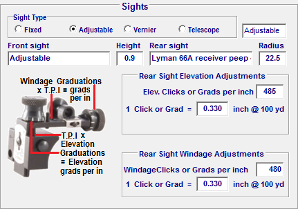
The "Graduations per inch" field requires some special consideration and it also is essential for the accurate calculation of the sight adjustment tables. Some adjustable sights consist of a sliding ramp or bar and these adjustments or calibrations per inch are either printed, inscribed or can be measured with a micrometer gage.
Sights with a threaded screw adjustment may have the threads per inch measured and then multiply that number by the number of spaces formed by the markings on the screw head in order to determine the graduations per inch. For instance, a Thompson Center, Renegade Muzzle Loading Rifle adjustable rear sight uses an adjusting screw having 40 threads per inch with the screw head marked off into six evenly divided sectors, thus resulting in (6 X 40 = 240) 240 graduations per inch. This value of 240 graduations should be entered into the "Graduations per inch" field.
When this entry is made in the Sight Elevation Graduations Per Inch field, an automatic calculation is performed, using the sight radius value and the graduations per inch value to calculate the movement of the bullet strike at 100 yards resulting from one graduation change of the adjustable sight. This calculated value is then auto-entered into the "bullet strike @ 100 yards" entry field.
The Sight Windage Graduations Per Inch uses the same procedure. However, the screw thread may be different than the elevation adjustment screw so the windage adjustment screw thread pitch must also be determined.
**************************************************************************************
VERNIER SIGHTS
If a Vernier type sight is used, the number of graduation marks per inch on the staff should be entered. The software will automatically calculated the further division of the graduation marks into points. (1/5 of each graduation mark) (20 graduations per inch on the staff results in 100 graduations per inch in the final Vernier Sight calculations) ( For Vernier Sights, the bullet strike @ 100 yards display may be divided by 5 to arrive at the amount of strike change per point adjustment) (Do not change the calculated display as the computer will make the division to determine the vernier point values.)
The Vernier Sight Windage Graduations Per Inch value may be determined by the same method as described above in the Adjustable Sights section.
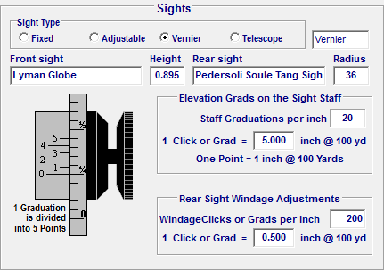
Graduations per inch as related to vernier sights is indicated by the number of elevation graduations per inch marked on the side of the vertical sight staff. Most are 20 per inch, some are 40 per inch and others use a different variation The vernier setup will usually allow sub-dividing each of the increments by 5. Therefore 20 graduations per inch will return100 points per inch, resulting in accurate adjustments of 1/100ths of an inch. In the case of a 36-inch sight radius this translates into one inch of vertical impact movement per point of adjustment at 100 yards.
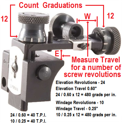
Most tang mounted vernier sights are equipped with windage adjustments that are graduated in approximately 1/2 minute of angle adjustments. A thread pitch of 40 t.p.i. that has the adjustment knob graduated in 5 segments will cause a 100 yard impact movement of 1/2 inch per segment adjustment when using a 36 inch sight radius. This means that the value entered into the windage graduation field would be 200 (40 thread per inch x 5 graduation marks on the knob = 200).
To determine the thread pitch on either elevation or windage adjustment screw on a sight, use a caliper or micrometer to measure the sight movement distance produced by 10 full turns of the adjustment stem and then divide 10 by the distance that the sight was moved by those 10 turns. 10 rotation of a 40 t.p.i. thread will move the adjustment 0.250 inches. Divide 10 by 0.25 and the result is 40. If the adjustment knob has 5 equally spaced graduations then multiply the thread pitch by the 5 graduations ( 5 x 40 = 200 ) and enter that value in the windage graduations per inch field. Most sight adjustment thread pitch sizes are standardized ( 28, 32, 36, 40, 44, 48, etc.) so select the closest match to your measurement and division results .
If either the adjustable or vernier sight radio buttons are selected, the elevation impact movement at 100 yards will be automatically calculated after the Graduations per inch are entered into the field.
**************************************************************************************
When a Fixed Sight configuration is chosen, the only sight value required is the height of the front sight above the center line of the bore. An accurate measurement can easily be made by using a caliper to measure the distance from the bottom of the barrel to the top of the sight and then subtracting one half of the diameter of the barrel where the sight is attached.
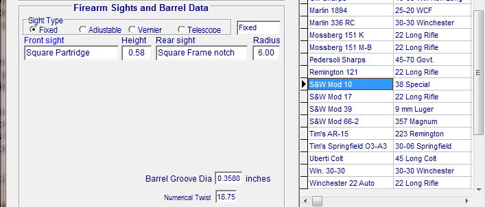
The Firearm Barrel Groove Diameter field records the distance value from the bottom of a rifling groove to the bottom of the opposite groove in the barrel. This is normally the diameter (in inches) of the bullet fired from the firearm. such as 30-06 = 0.308", 45 Cal pistol = 0.452", 45 Cal Rifle = 0.458", etc. Slugging the firearm bore and measuring the slug will reveal the exact bore diameter.
After the entry fields all have the correct values, click the ![]() button. This will enter the name of the firearm and the correct sight configurations into a permanent record that may then be retrieved and sent to the Data Entry page to be used in the Ballistics and Trajectory calculations.
button. This will enter the name of the firearm and the correct sight configurations into a permanent record that may then be retrieved and sent to the Data Entry page to be used in the Ballistics and Trajectory calculations.
Copyright 2002-2010. TMT Enterprises. All rights reserved.